










Repeating Toolpaths Using Copy Transformation Instructions In 3Dexperience DELMIA
Written by: Tom Buxton
Published: Aug 11, 2026
| View All Blogs
One of the most overlooked productivity gains in DELMIA Machining comes from the ability to reuse and replicate toolpaths using the Copy Transformation Instruction tool.
Instead of rebuilding machining strategies feature by feature, manufacturers can duplicate proven toolpaths and apply them across similar geometry in seconds. Whether you’re machining repeating pockets or mirrored components, this capability eliminates repetitive work while ensuring consistency across the entire part.
3D Experience DELMIA provides a faster way of programming allows for more time optimizing processes rather than recreating them.
Copy Transformation Tool In DELMIA – Key Capabilities
Translation
Move a toolpath from one location to another using a defined direction and distance.
This is ideal for repeating features such as linear hole patterns or multiple identical pockets—simply program once and reposition as needed.
Example
20 identical components have been nested onto a singular sheet.
Each component is separated 50mm apart in both the X and Y axes (measurement taken from the centre point of the component bounding box).
Using the translate option, a linear dimension can be applied to copy the toolpath.

Nesting plate for translation
Select the copy transformation tool and select translate for the transformation type.
Select the plus symbol and choose the operation to be copied.
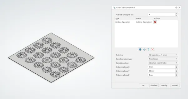
Translate Copy Transformation
Specify the first direction required using the spacing in X,Y,Z.
Simulate the toolpath and select ‘OK’.
For the second direction, enter the copy transformation tool again and repeat the process.
This time, use the original operation as well as the first copy direction for items to copy and specify the distance in the second direction.

Translate in second direction
Rotation
Rotate a toolpath around a chosen axis by a specified angle.
Perfect for circular patterns, such as evenly spaced features on flanges or rotational components, ensuring each instance is identical.
Example:
Two pockets repeat around a central axis.
Each pocket is repeated four more times around the central axis with a spacing of 72deg.
Using the rotation option, both toolpaths can be copied to the other iterations.

Original pocket toolpaths for rotation
Select the copy transformation tool and select the axis of revolution (can be specified using either a circular edge or a coordinate system.
Specify rotation for the transformation type.
Enter the required copies and angle step.
Select the plus symbol and choose the operations to be copied.
Simulate the toolpath to ensure angle step is correct and select ‘OK’.

Completed Rotation Copy Transformation
Mirror
Create a mirrored version of a toolpath across a selected plane.
For symmetrical parts, this removes the need to recreate operations for opposite-hand features, maintaining consistency while cutting programming time in half.
Example
A plate with a company logo to be mirrored onto the back face.
A prismatic roughing toolpath has cut the logo on one side.

Company logo toolpath – prismatic roughing
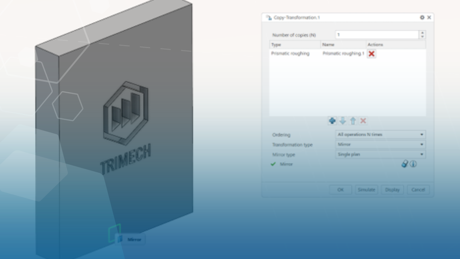
Enter the copy transformation tool and specify mirror in the transformation type dropdown.
For this case, leave the number of copies count at 1.
Select the mirror plane/face.
Run the toolpath simulation and select ‘OK’.

Mirror copy transformation dialogue box
The copied toolpath is an exact mirror of the initial toolpath.

Final toolpaths for mirror transformation
Axis to Axis
Reapply a toolpath by aligning it from one coordinate system or axis to another.
This is especially valuable in multi-face machining, where the same strategy can be reused across different orientations or setups.
Example
A six-sided dice each with the same hemisphere cuts across all faces.
After creating the initial toolpath, multiple machining axes have been created for repeating the toolpath.

Six-sided dice with toolpath and axes
Select the copy transformation tool and select the axis to axis option from the transformation type dropdown menu.
Select ‘from’ to choose the initial toolpath machining axis system and ‘to’ to place the copied toolpath machining axis system.
Select the plus symbol and choose the operations to be copied.

Axis-to-axis over planar face
Axis-to-axis is not restricted to the same face. So long as the tool axis is pointing in the correct direction, the toolpath can be applied at any angle.

Axis-to-axis over 90 degrees
Conclusion
Together, these transformation options reinforce a simple but powerful principle: once a toolpath works, it can work everywhere—accelerating programming, improving consistency, and unlocking a more efficient machining workflow
Categorised as: Design | Education | SOLIDWORKS xDesign | Software
Get a SOLIDWORKS Quote
Interested in SOLIDWORKS? Contact us for questions, trials, or demos by clicking the button below or call 01926 333777. Our experts will help you find the perfect solution.

Related Posts

How to Find Reaction Forces in SOLIDWORKS Simulation
SOLIDWORKS helps us to find resultant forces through simulation studies. These virtual tests reduce the need for physical prototypes and give us an accurate answer.

Setting number of decimal places in a table on a drawing
When creating an equation in a drawing general table, is it possible to define the…
SOLIDWORKS Smart Fasteners
SOLIDWORKS Smart Fasteners is a really useful time saving tool, allowing you to automatically insert toolbox fasteners such as bolts and screws into an assembly providing there is a standard hole.
Why is my Flat Pattern not showing in SOLIDWORKS Drawings?
This may be linked to how the drawing is saved or it can be related to how sheet metal parts are displayed in drawings, read on to find out how to fix it.

SOLIDWORKS Tips: Are you Making this Common Mistake in Fatigue Analysis?
Simulation is a vital and complex engineering need. Fortunately, SOLIDWORKS makes it easy to test, correct mistakes and obtain accurate results.
Series 1 Land Rover Pedal Car – Made Easy with Solidworks!
The Series1 began production in 1948 designed to help get Britain farming after the war effort. It grew extremely popular and today enthusiasts are prepared to throw their life savings at restoring originals from that period.

SOLIDWORKS Visualize. Why go pro? – 6 Post Processing
In this blog we will be look at the post-processing options that can be found in SOLIDWORKS Visualize

SOLIDWORKS Visualize. Why go pro? – 7 Lighting
SOLIDWORKS Visualize uses a non-biased rendering engine, which allows for physically accurate lighting within a scene. It generates images with high amount of realism and correct set up can replicate photo studio lighting.

How to Get Your Serial Number for SOLIDWORKS Visualize Standard
Want to download Visualize to make photorealistic renders? Follow this guide for accessing your Visualize serial number that comes bundled in with SolidWorks Professional and Premium.

How to Recover SOLIDWORKS Files After a Crash
SOLIDWORKS has two different methods to help you recover from an unexpected crash or loss of data in the form of auto-recovery and back-up settings.