






Sheet Metal Fabrication
SOLIDWORKS Sheet Metal
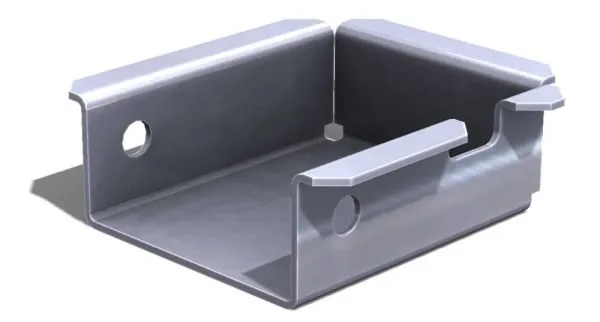
SOLIDWORKS Sheet Metal tools provide a specialised environment for designing complex metal parts and assemblies.
The system automates the creation of flat patterns and manufacturing data, ensuring that what you design in 3D can be accurately produced in the shop.
Key Capabilities
Ready to eliminate the guesswork from your fabrication process?
Learn how sheet metal in SOLIDWORKS works with a demo from our experts or get hands on to become familiar with the tools at one of our sheet metal training courses.

Customer Testimonial - Loma Systems
Sheet metal is very important for Loma. We have a huge amount of sheet metal work including weldments and that's something that's really saved us a lot of time.
In our production base we have some computers which allow the production team to access design information and assemblies so they can see how the assembly is meant to go together, they can measure from that and that means that they don't have to disturb engineers and stop the engineers from doing their work.
Sean Hannan
Business Systems Manager at Loma Systems
Frequently Asked Questions
SOLIDWORKS uses Bend Allowance, Bend Deduction, or K-Factor to account for the material stretching that occurs during the bending process.
You can use standard tables or input your own company-specific values to ensure the flat pattern perfectly matches your workshop’s brake press results.
Yes. Using the "Convert to Sheet Metal" command, you can select a base face and edges to rip, and SOLIDWORKS will automatically transform a solid block or an imported STEP file into a thin-walled part with folding and unfolding intelligence.
The relationship is fully parametric and associative. If you change a flange length, a hole position, or the material thickness in the 3D model, the flat pattern and any exported 2D drawings update automatically in real-time.
You can use the Forming Tools library. SOLIDWORKS allows you to drag and drop standard shapes (like vents, ribs, or lances) onto your part.
You can also create your own custom forming tools from any 3D shape to represent bespoke tooling used in your factory.
Absolutely. You can right-click the flat pattern and select "Export to DXF/DWG."
This allows you to strip away unnecessary geometry and export only the outer profile, inner holes, and (optionally) the bend lines on specific layers for your nesting software.