









Getting Started With Wire EDM In 3DExperience DELMIA
Written by: Tom Buxton
Published: Sep 2, 2026
| View All Blogs
Programming Wire EDM machines can be a complex and time-consuming task, particularly when dealing with intricate geometries, tight tolerances, and demanding surface finish requirements. DELMIA Wire EDM addresses these challenges by providing an intelligent programming environment that automates key tasks, validates machining strategies through simulation, and helps users achieve optimal cutting performance with confidence.
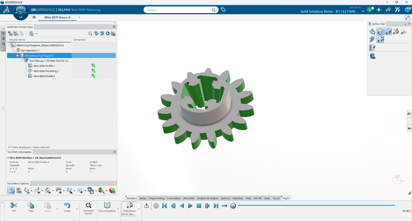
Completed Wire EDM study
An Overview Of The Nesting Setup Tool
DELMIA Wire EDM provides a comprehensive programming environment that helps manufacturers efficiently create, validate, and optimise Wire EDM operations. Supporting both 2-axis and 4-axis machining, it enables the production of complex geometries and tapered features with precision and consistency.
As part of the 3DEXPERIENCE platform, DELMIA Wire EDM also provides seamless integration between design and manufacturing, ensuring digital continuity from engineering through to production. Combined with machine-specific NC code generation, these capabilities help manufacturers improve productivity, reduce errors, and achieve right-first-time machining results.
Wire EDM Case Study
Part operation setup
Select ‘import and mount resources’ to select a preexisting WireEDM machine. Alternatively, select ‘generic machine’ to generate a default machine.
Once a machine has been imported, double click the ‘part operation’ in the activities process view tab.
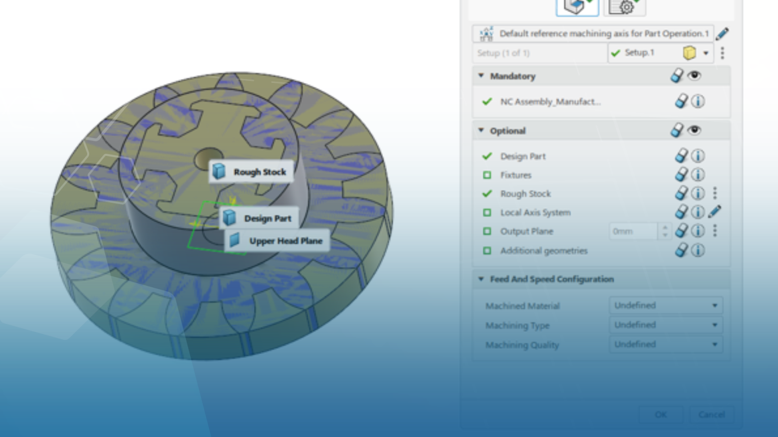
At this point, the machining axis, part body and stock can be assigned.
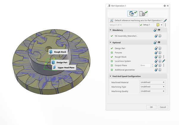
Part setup window
Ensure the machining axis has Z pointing up. The wire will be running parallel to this axis.
Select the design part and stock, then select ‘OK’ to complete the part setup.
Importing tools
If a wire tool has already been created, select ‘tool and assembly search’ from the setup tab. From there, the correct tool can be found and applied to the program.
Alternatively, a new tool can be created by selecting ‘Wire Tool’ option from the setup tab. The tool name, diameter and material can be assigned from there.
2 axis profile operations
To begin a profile operation, enter the Wire EDM tab and select ‘Wire Profile’.
The tool should be automatically defined.
A prompt will appear to create a new feature, select the large plus symbol to begin creating a profile feature.
At this point, select the edges for the main contour as well as the threading point. These two components are mandatory for creating a Wire EDM feature.
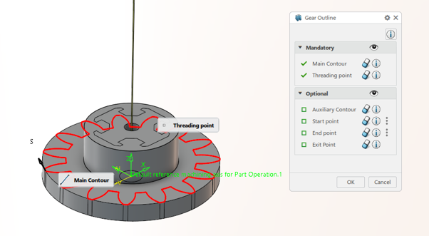
2 axis profile feature
Once the feature has been created, the profile operation can be generated.
The geometry tab will allow any axial or radial offsets to be applied. A part height can also be implemented at this stage.
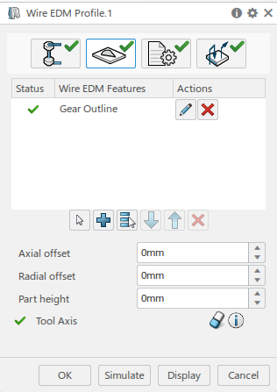
Profile operation geometry tab
From the strategy tab, further operation details can be applied. Options include number of passes and cut the wire at end, as examples.
For the 2-axis variation, leave the axis strategy as ‘fixed’. This will ensure the wire always remains parallel with the machining axis.
The final tab, macros, will allow for approach and retract movements to be applied. These can be prebuilt options or built by the user.
Once the strategies and macros have been generated, select simulate.
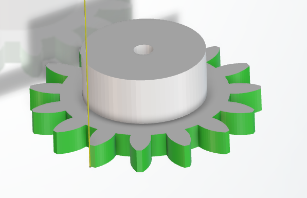
Gear outline profile operation
Pocketing
Within the Wire EDM tab, ‘Wire pocketing’ can be chosen.
Similarly to the profile operation, a Wire EDM feature must be created.
The mandatory components to a pocket operation are main contour and threading point.
If a hole already exists within the pocket, a hole diameter can be applied within the geometry tab. Note: the centre point of the hole is coincident with the machining axis.
From the strategy tab, a cutout contour can be applied. The pocket operation will now cut all material between the main contour and the cutout contour. The profile can be any shape. Furthermore, this option can be used instead of the hole diameter if the pocket is not in line with the machining axis.
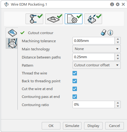
Wire EDM pocketing strategy tab
The macro tab can be used to control the approach and retract movements of the operation.
Once all options have been chosen, select ‘simulate’ to generate a toolpath.
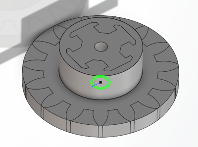
Wire EDM Pocketing toolpath
4 axis profile operations
Wire EDM can also be used over 4-axes. This example will be using a profile operation, implementing two contours.
Upon selecting ‘Wire profile’ from the Wire EDM tab, the mandatory main contour and threading point can be chosen.
Note: the smaller of the two profiles is always the main contour.
The second profile can be selected by applying an auxiliary contour.
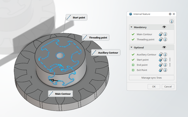
Feature selection options
When using 4-axis Wire EDM, it is vital to ensure all sync lines are correct. This acts as a point-to-point system between any vertices of the profiles. Select ‘manage sync lines’.
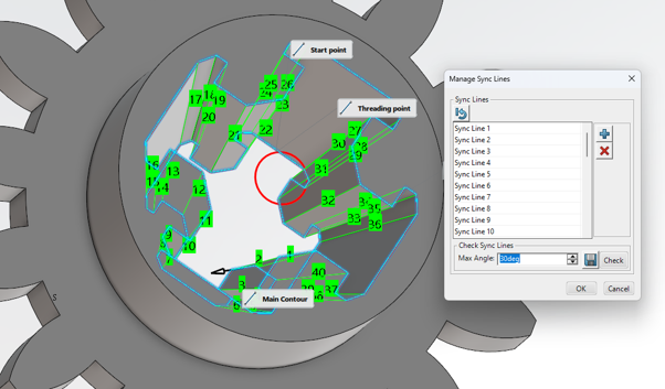
Manage sync lines
If any lines are not correct. Select the red cross to remove the line and the plus symbol to re-enter.
Lines can be generated by selecting a vertex and then the corresponding vertex on the opposing profile.
The geometry, strategy and macro tabs remain the same as the 2-axis approach for profiling. However, in the strategy tab, go to axis strategy and chance the strategy dropdown to ‘between contours’.
This will implement the 4-axis strategy.
Select ‘Simulate’ to generate a toolpath.
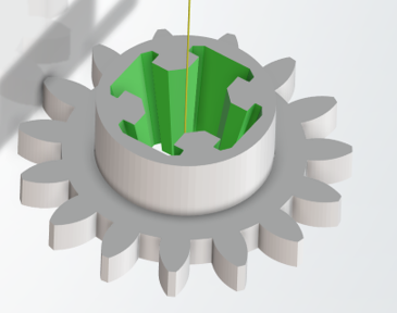
Complete 4-axis profile operation
Categorised as: Design | Education | SOLIDWORKS xDesign | Software
Get a SOLIDWORKS Quote
Interested in SOLIDWORKS? Contact us for questions, trials, or demos by clicking the button below or call 01926 333777. Our experts will help you find the perfect solution.

Related Posts

How to Find Reaction Forces in SOLIDWORKS Simulation
SOLIDWORKS helps us to find resultant forces through simulation studies. These virtual tests reduce the need for physical prototypes and give us an accurate answer.

Setting number of decimal places in a table on a drawing
When creating an equation in a drawing general table, is it possible to define the…
SOLIDWORKS Smart Fasteners
SOLIDWORKS Smart Fasteners is a really useful time saving tool, allowing you to automatically insert toolbox fasteners such as bolts and screws into an assembly providing there is a standard hole.
Why is my Flat Pattern not showing in SOLIDWORKS Drawings?
This may be linked to how the drawing is saved or it can be related to how sheet metal parts are displayed in drawings, read on to find out how to fix it.

Why is SOLIDWORKS Crashing?
It’s one of the great mysteries of life – why is SOLIDWORKS crashing? Let’s explore how SOLIDWORKS crashes and how we can improve performance in SOLIDWORKS.

SOLIDWORKS Tips: Are you Making this Common Mistake in Fatigue Analysis?
Simulation is a vital and complex engineering need. Fortunately, SOLIDWORKS makes it easy to test, correct mistakes and obtain accurate results.
Tech Support Blog: Why are my SOLIDWORKS BOM Quantities Wrong?
Why are my SOLIDWORKS BOM Quantities Wrong? A support call cropped up this week which…
Series 1 Land Rover Pedal Car – Made Easy with Solidworks!
The Series1 began production in 1948 designed to help get Britain farming after the war effort. It grew extremely popular and today enthusiasts are prepared to throw their life savings at restoring originals from that period.

SOLIDWORKS Visualize. Why go pro? – 6 Post Processing
In this blog we will be look at the post-processing options that can be found in SOLIDWORKS Visualize

SOLIDWORKS Visualize. Why go pro? – 7 Lighting
SOLIDWORKS Visualize uses a non-biased rendering engine, which allows for physically accurate lighting within a scene. It generates images with high amount of realism and correct set up can replicate photo studio lighting.