







Multiaxis Drilling in SolidCAM: Programming Complex Angled Holes with Confidence
Written by: Tom Buxton
Published: Aug 18, 2026
| View All Blogs
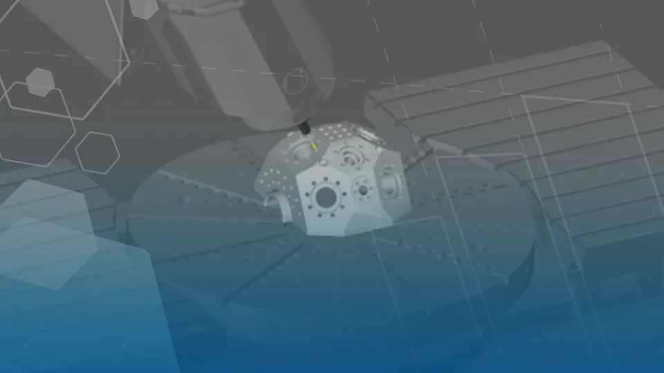
Manufacturers are increasingly being asked to produce components with complex geometries, multiple faces and holes positioned at a variety of angles. Multiaxis Drilling in SolidCAM: Programming Complex Angled Holes with Confidence addresses these challenges, helping programmers efficiently machine complex angled holes while maintaining accuracy and reducing programming time. While these parts deliver improved product performance, they can introduce significant programming challenges when it comes to CNC machining.

The process of Multiaxis Drilling in SolidCAM is a simplified operation, allowing programmers to automatically identify and machine holes in different orientations while benefiting from advanced collision avoidance, machine awareness and simulation tools.
Why Multiaxis Drilling in SolidCAM Matters
Traditionally, machining holes located on multiple faces of a component could require multiple setups, manual feature selection or extensive programming effort. This not only increases programming time but can also introduce opportunities for error.
The Multiaxis Drilling in SolidCAM operation is designed to streamline this workflow by combining automatic hole selection with multiaxis positioning strategies. The result is a faster and more reliable approach to drilling, tapping and boring operations on complex parts.
Automatic Hole Selection Reduces Programming Time
One of the most powerful aspects of Multiaxis Drilling is the ability to automatically locate holes across the model.
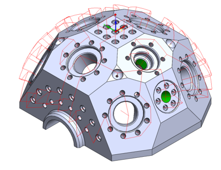
After creating a Multiaxis Drilling operation, users can leverage the Find Holes functionality to identify relevant drilling features automatically. Rather than manually selecting each hole and orientation, SolidCAM analyses the model and groups the features ready for machining.

For components containing dozens or even hundreds of holes on multiple faces, this can dramatically reduce programming effort while improving consistency across operations.
The software then determines the required tool orientations, helping to remove much of the complexity traditionally associated with multiaxis drilling strategies.
Intelligent Collision Avoidance for Safer Machining
Programming a multiaxis operation is only part of the challenge. Ensuring the tool, holder and machine can physically access every feature without interference is equally important.
SolidCAM enables gouge checking and collision detection against selected model surfaces. Users can include holder and arbor checking while defining critical surfaces to avoid during machining.
With these controls in place, SolidCAM can:
- Detect potential collisions before machining begins
- Consider holder and adaptor geometry
- Optimise machine movements between drilling positions
- Reduce the risk of costly machine crashes or part damage
This level of machine awareness is particularly valuable when machining highly featured aerospace, energy, medical or precision engineering components where access is often restricted.
Verify Before You Cut
A key advantage of the SolidCAM workflow is the ability to validate machining strategies before a single chip is cut.
Once the drilling operation has been calculated, programmers can use both SolidVerify and full Machine Simulation to analyse the toolpath and machine movement.

SolidVerify provides rapid material removal simulation, helping users confirm that all required features are machined correctly. Machine Simulation goes a step further by validating machine motion, rotary axis positioning and component accessibility.
This digital verification process reduces shop-floor uncertainty and gives programmers greater confidence before releasing NC code to production.
Conclusion: More Efficient Five-Axis Drilling Workflows
As part complexity continues to increase, manufacturers need programming tools that can keep pace without increasing risk or programming overhead.
SolidCAM’s Multiaxis Drilling module combines automatic hole recognition, intelligent machine positioning, collision avoidance and integrated simulation. For SOLIDWORKS users already leveraging SolidCAM, it provides a practical route to programming complex angled-hole components while maintaining accuracy, reducing setup effort and improving confidence in the final machining process.
If your team is programming complex multiaxis components, reviewing the end-to-end CAM setup, toolpath strategy and simulation workflow can help identify where programming time and shop-floor risk can be reduced.
Categorised as: Industry Insight | Manufacturing | News | SolidCAM
Get a SOLIDWORKS Quote
Interested in SOLIDWORKS? Contact us for questions, trials, or demos by clicking the button below or call 01926 333777. Our experts will help you find the perfect solution.

Related Posts

How to come up with ideas for your design or engineering project – some helpful tips
We know coming up with an interesting and creative design or engineering project can be…
Design considerations when 3D printing
3D printing is a colloquial term used to generalise a family of additive manufacturing processes. At the consumer level the most common 3D printing process is Fused Deposition Modelling (FDM) – a technique whereby thermoplastics are extruded through a nozzle, and a part is built up layer by layer. FDM is very popular with hobbyists due to the relatively low cost of the printer, alongside the wide range of properties and appearances thermoplastics present. The conveniency to turn a custom CAD model into a product in a short space of time is a superb way to make life easier.
Why should I be nesting parts?
Firstly we should define what is nesting? Nesting is like putting the pieces of a jigsaw together, it is the process of creating an optimal layout of your flat parts so that you get the most out of your material. Typically this process would be used in the sheet metal, fabric, plastic and wood/joinery markets. Nesting can also be used to align parts with a specific grain such as brushed metal products, patterned materials or wood grain.

Press Release: TriMech and Solid Solutions Unite
TriMech has acquired Solid Solutions Group, bringing together hundreds of technical specialists from across four countries, and expanding support for design engineers and manufacturers in North America, the UK, and Ireland.
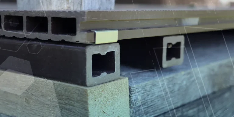
Top 4 Benefits of Composite Materials for Lightweight Engineering
One method design and engineering teams have employed to combat high costs and high carbon emissions is the use of composite materials in the development of parts.

Hydrogen-Powered Aircraft: What are the Challenges?
In aviation industry, we’re seeing the rise of eVOTL concepts which challenge the traditional ideas…

February Customer Spotlight
Across every industry, whatever size, we are continually impressed and proud to support our customers. Check out how they are transforming their industries through innovation…
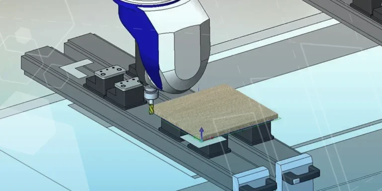
SWOOD Licensing Explained
Learn the differences between SWOOD licensing. Understand how online licences connect to Eficad’s server for flexibility, while network licences allow shared access across multiple users. Discover which option suits your workflow.
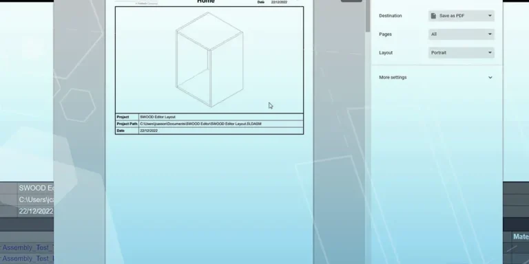
How to Install and Use SWOOD Editor
Customisable SWOOD reports provide a comprehensive set of documentation for production including cutting lists, hardware lists, labels, and material summaries.
Solid Solutions Signs Catalyst Platinum Partnership
The partnership will be pivotal in providing 3D Computer Aided Design (CAD) training to members of all backgrounds in the Catalyst ecosystem, from students and younger people up to experienced entrepreneurs.