







FEA Simulation: What is Element Deactivation Used For?

Written by: Tom McHale
Published: Oct 20, 2023
| View All Blogs
We were recently asked what the term ‘element death’ meant in the context of finite element analysis (FEA) and what would it be used for.
Simply put, this refers to the turning off or removal of elements from a running analysis.
There are two types of element death or element deactivation, and this blog explores them both while alongside what they are used for.
AUTOMATIC ELEMENT DEACTIVATION
One type involves removing an element from a simulation once the material constituting it has failed.
This could be via a mechanism, such as the impact of a bird on the leading edge of a composite wing where, once the layup has failed, you want to see what the bird hits next for its secondary impact(s).
Similarly, in a joule heating analysis you might ‘kill’ ice elements as they melt.
Either way, the removal is automatic and triggered by logic in the solver that is defined before you start the analysis.
MANUAL ELEMENT DEACTIVATION
The other type is more manual, where you as the analyst decide to remove some elements at a point in the solution to see what happens as load paths change.
Why would you do this? Examples where this might be a useful thing could be:
- Simulating the sudden elimination of a prop supporting a steel structure – you preload the structure with the prop in place and then turn it off to see how the load redistributes to the structure during a sudden removal and if failure ensues.
- Where part of an airframe is suddenly eliminated due to a ballistic impact.
- Simulating the removal of support structures from a 3D printed component, and how the frozen-in stresses redistribute and distort the part.
ELEMENT DEACTIVATION CASE STUDY
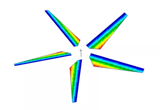
To illustrate how simple this can be, and the kind of information you can get from it, we’ll use an example based on based on some work for a client around 20 years ago.
They had a rotating propellor and wanted to see the impact of the sudden loss of one of the blades on the forces in the bearings. For this illustration, we’re not applying the pressure distributions from the airflow, just spinning up the propellor to 2400 RPM and then shutting off one of the blades.
In the real case, we used a user sub-routine to calculate loads on the blade based on speed and orientation.
Fortunately, MSC Marc makes this very easy.
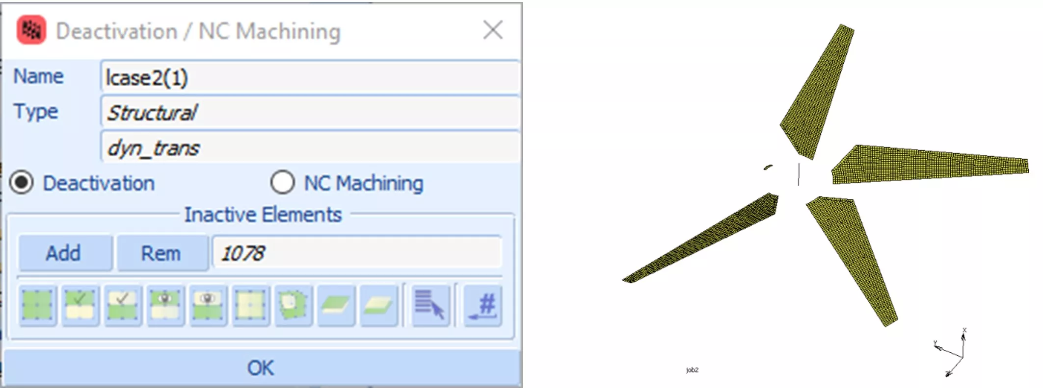
We found using an initial velocity condition to set the blades in motion took a lot more solution time to settle than spinning the blades up to 2400 RPM from stationary, so a ten-second-long transient step was run to reach full speed.
In the second step we deactivate one blade set of elements by simply nominating the ones to remove.
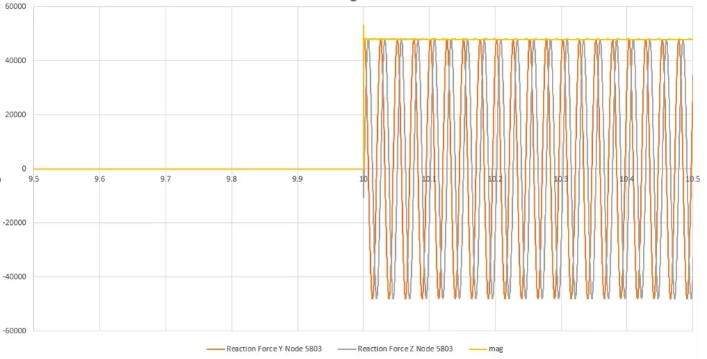
Looking at the reaction forces at the base of the shaft we can see at the moment the blade is deactivated the lateral reaction forces in the constraint that represents the shaft bearing change dramatically as the rotor becomes imbalanced.
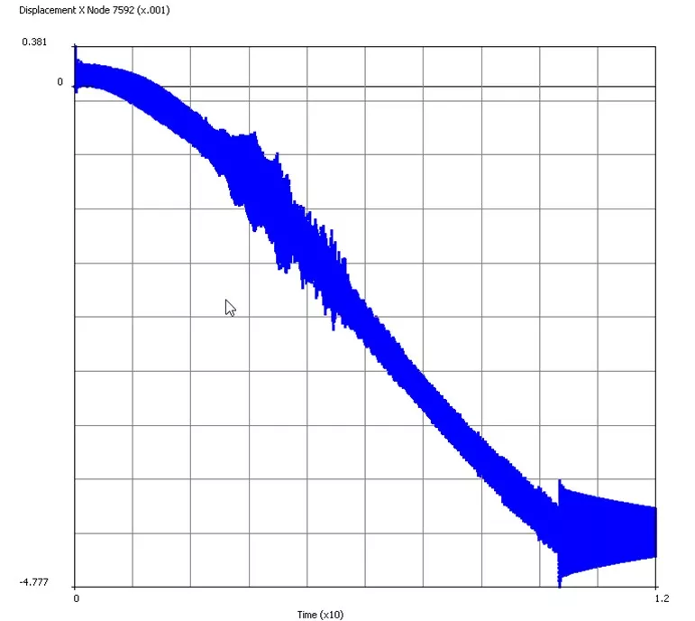
We can also look at the tip displacement of one of the remaining blades.
As the speed builds, we see an increase in out of plane deflection rise as the centrifugal load bends the blade. There’s some underlying vibration with an increase at around 4s as we pass through the first bending mode of the blade and then a larger excitation at t=10s when the fifth blade disappears.
If we were interested in the effects of different blade fractions or multiple blade-loss scenarios we could save a lot of time by writing a restart file after the end of the spin up simulation and restart multiple different jobs from that with different failure conditions.
MSC Marc is available under the MSC One token licensing scheme and is a very powerful non-linear FEA solver, renowned for its robust contact and handling of very large strain simulations.
A broad set of user subroutine interfaces also makes it a very flexible tool for users at the cutting edge of what can be done.
If you are interested in this, or have other difficult non-linear problems please get in touch with us to discuss how we might be able to help.
Categorised as: Simulation | Tech Tips
Start Your Free SOLIDWORKS Trial
Get a FREE trial of 3D CAD SOLIDWORKS to experience the capabilities of SOLIDWORKS Premium and SOLIDWORKS Visualize.

Related Posts
How to Find Reaction Forces in SOLIDWORKS Simulation
SOLIDWORKS helps us to find resultant forces through simulation studies. These virtual tests reduce the need for physical prototypes and give us an accurate answer.

Setting number of decimal places in a table on a drawing
When creating an equation in a drawing general table, is it possible to define the…

Why is my Flat Pattern not showing in SOLIDWORKS Drawings?
This may be linked to how the drawing is saved or it can be related to how sheet metal parts are displayed in drawings, read on to find out how to fix it.
Why is SOLIDWORKS Crashing?
It’s one of the great mysteries of life – why is SOLIDWORKS crashing? Let’s explore how SOLIDWORKS crashes and how we can improve performance in SOLIDWORKS.

SOLIDWORKS Tips: Are you Making this Common Mistake in Fatigue Analysis?
Simulation is a vital and complex engineering need. Fortunately, SOLIDWORKS makes it easy to test, correct mistakes and obtain accurate results.

Tech Support Blog: Why are my SOLIDWORKS BOM Quantities Wrong?
Why are my SOLIDWORKS BOM Quantities Wrong? A support call cropped up this week which…
How to Get Your Serial Number for SOLIDWORKS Visualize Standard
Want to download Visualize to make photorealistic renders? Follow this guide for accessing your Visualize serial number that comes bundled in with SolidWorks Professional and Premium.
How to Recover SOLIDWORKS Files After a Crash
SOLIDWORKS has two different methods to help you recover from an unexpected crash or loss of data in the form of auto-recovery and back-up settings.
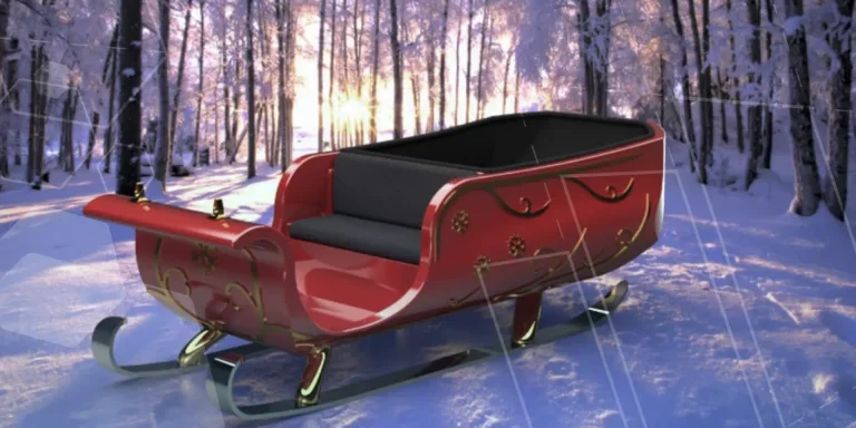
Redesigning Santa’s Sleigh in SOLIDWORKS
Every year Father Christmas has to fly in his sleigh to deliver presents to boys and girls all over the world in just one night. To put this into perspective, it takes a little under 24 hours to fly from London (UK) to Sydney (Australia) in a streamlined Boeing 747, whereas Father Christmas’ mode of transport is believed to be a rather non-aerodynamic sleigh.

Radiation in Flow Simulation – Part 1 : Reflection
Technical Manager Andy Fulcher explores ‘Radiation in Flow Simulation, Part 1 : Reflection’