








Efficient modelling of machinery components

Written by: Tom McHale
Published: May 23, 2023
| View All Blogs
MSC Adams is a multibody dynamics modelling package. Its heritage is in suspension modelling for automotive applications but it is also widely used in machinery components design. One of the factors that makes it a popular choice is the Adams Machinery toolkit available as a plug in. Adams Machinery is all about saving time – in terms of your simulation time, but also your time to market.

MSC Adams Gear Model
Gear Modelling
Before Adams Machinery, we had a few options for simulating gear meshing within a system. We could specify a coupler between two rotating shafts that coupled their motion with a specified gear ratio. It’s quick and dirty, but it doesn’t given you critical output like backlash values, where a change in direction of the gear rotation leads to a ‘pause’ in the coupling while gaps are taken up between the mating teeth. This also means we don’t get any vibrational input to the system which might be important if it’s driving e.g. fine optics or a laser communication device. The other end of the spectrum was to import 3D cad of the gear set and specify contact between the components. This adds a huge burden to the solution slowing things down dramatically, and the resulting output can be quite noisy due to contact chatter. The intermediate approach involved generating your own functions that relate speed and position between the two shafts, which is fine for a specialise but not ideal for the designer who occasionally wants to model some gears.
Adams Machinery Gear introduces options through a simple wizard toolkit and creates all the entities you need relative to the rest of your system. Gear pairs can be represented at any of four levels of fidelity.
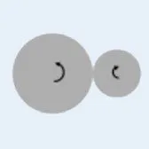
Coupler: This is the simplest spur gear relationship where the gear ratio only is input in the same way as described above. It can be easily stepped up to one of the higher fidelity representations so you can use it initially to get a model running and then refine your representation.

Simplified: This adds the ability to represent helical, bevel and planetary gear systems. It uses an analytical approach to represent backlash and calculate contact forces very quickly.

Detailed: For spur gears this upgrades the analytical approach with an involute function and can calculate up to three simultaneous gear teeth interactions with frictional effects.
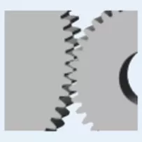
3D Contact: Without having to go back to CAD and create a 3D model of the gear pair, this option automatically generates the solid body from parameters for spur, helical and bevel gears. Backlash is now based on the actual geometry and centres distance and out of plane misalignment can be considered.
Implementing any of these in the model is simply a question of answering some questions about e.g. the number of teeth, gear depth etc and identifying what and where they attach to the assembly.
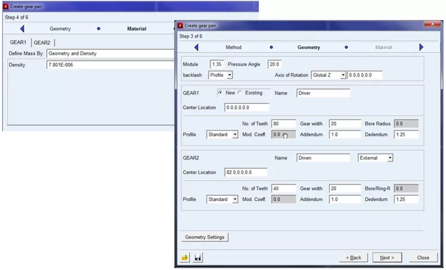
Creating a gear pair
We can see the benefits of the different levels of fidelity through an example. Let’s say we are using a gear set with a stepper motor to position a platter, like in the video above we might get a backlash plot something like what is shown below. This is essentially a plot of the angular position of the driven gear shaft with respect to where it should have been without backlash and comparing the Simplified, Detailed and 3D Contact representations.
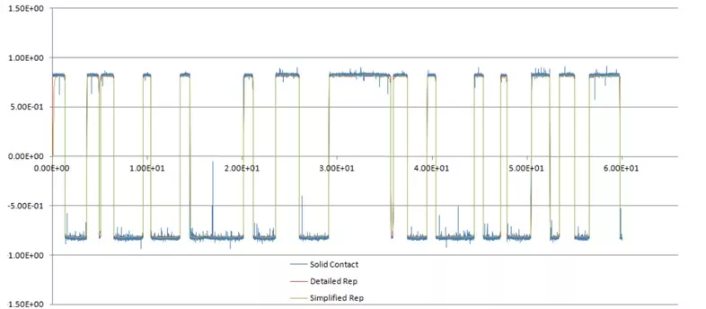
3D Contact Model
What’s obvious is the chatter from the 3D contact model. This can be fine-tuned out with adjustments to the Hertzian contact model to some degree, but is always present. If we zoom in on the plot we can see more.
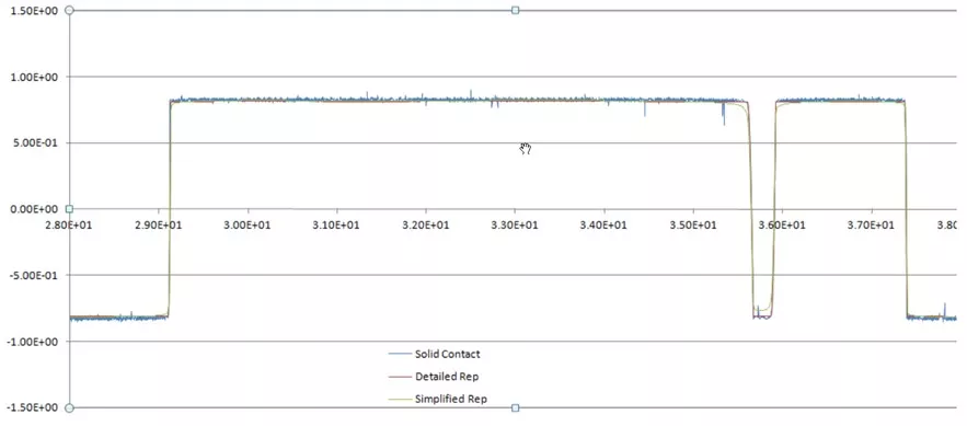
3D Contact Model – Zoomed in
You can see the effect of using the simplified model here – there’s cutting of the corner compared with the 3D and Detailed model, which with a sudden reversal of direction actually clips the magnitude. To understand fully the effect on simulation, consider the runtimes for the three models. The Simplified model took 33 seconds, the Detailed 73 seconds while the 3D contact took 1 hour 22 minutes. It’s clear that the detailed model gives you a good response in an acceptable solution time.
Adams Machinery
If you want to go further with machinery modelling, Adams Machinery has modules for belts, chains, cables, cams, motors and bearings. These modules offer similar model fidelity enhancements with little extra manual and solver effort.

MSC Adams Mower

MSC Adams Rudder
Adams Gear AT module
If you want to go further with gears Adams has the Gear AT module adds in the flexibility of the gear teeth under load, and MSC Marc’s analytical contact is brilliant at getting accurate contact stressed from sliding contact.
 MSC Adams Worm Gear
 MSC Adams Planet Gear
 MSC Adams Tooth Breaking
All these solutions are available under the MSC. One unified license scheme which enables all the MSC core products in a flexible way meaning you can choose the right tool for whatever job is in front of you.
If you’d like more information or would like to discuss how advanced simulation tools could reduce and improve your design process, please get in touch.
Categorised as: Simulation
Get a SOLIDWORKS Quote
Interested in SOLIDWORKS? Contact us for questions, trials, or demos by clicking the button below or call 01926 333777. Our experts will help you find the perfect solution.

Related Posts
How to Find Reaction Forces in SOLIDWORKS Simulation
SOLIDWORKS helps us to find resultant forces through simulation studies. These virtual tests reduce the need for physical prototypes and give us an accurate answer.

SOLIDWORKS Tips: Are you Making this Common Mistake in Fatigue Analysis?
Simulation is a vital and complex engineering need. Fortunately, SOLIDWORKS makes it easy to test, correct mistakes and obtain accurate results.
Redesigning Santa’s Sleigh in SOLIDWORKS
Every year Father Christmas has to fly in his sleigh to deliver presents to boys and girls all over the world in just one night. To put this into perspective, it takes a little under 24 hours to fly from London (UK) to Sydney (Australia) in a streamlined Boeing 747, whereas Father Christmas’ mode of transport is believed to be a rather non-aerodynamic sleigh.

Radiation in Flow Simulation – Part 1 : Reflection
Technical Manager Andy Fulcher explores ‘Radiation in Flow Simulation, Part 1 : Reflection’
Radiation in Flow Simulation – Part 2 : Refraction
Technical Manager Andy Fulcher explores ‘Radiation in Flow Simulation, Part 2 : Refraction’
The Coanda Effect in Flow Simulation
Can you take advantage of the Coanda Effect & can SOLIDWORKS Flow simulate it? Applications Engineer Romel Cumare investigates in his latest blog post.
So how accurate is SOLIDWORKS Simulation?
How accurate is SOLIDWORKS Simulation? Elite Applications Engineer Chris Boyles investigates.
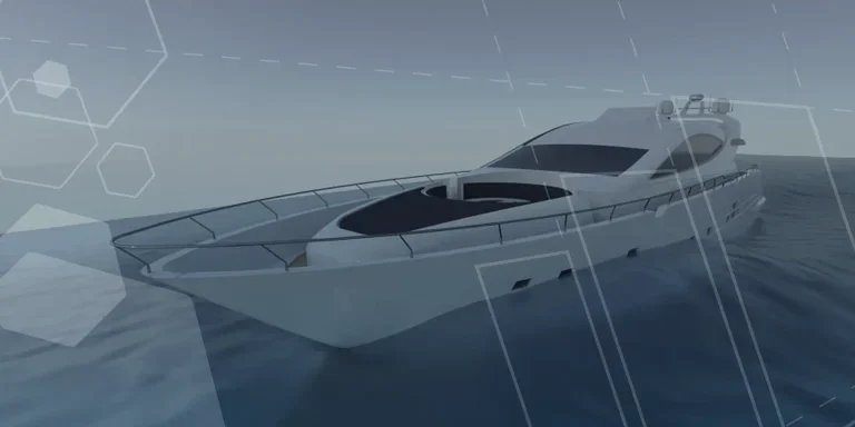
Set Your Fluids Free with SOLIDWORKS Flow Simulation
A look at the new Free Surface feature coming in SOLIDWORKS Flow Simulation 2018.
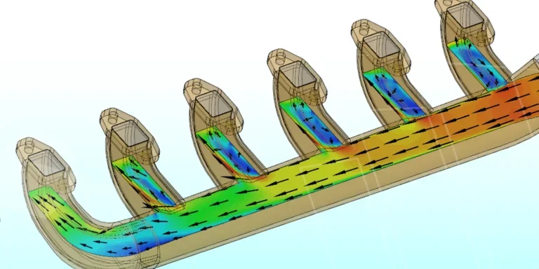
Finding a Good Mesh Fast in SOLIDWORKS Flow Simulation
‘How do I know when to stop my calculation?’ and ‘How do I know my mesh is good enough?’ are questions often asked when running SOLIDWORKS Flow Simulation studies.
The answer is to ensure the solution reached is both fully converged AND mesh independent. In practice this can take a bit of trial and error as well as some experience in the process. However, SOLIDWORKS Flow can help us do both of these at once! Here’s how…

Free Surface Evaluation & Validation – SOLIDWORKS Flow Simulation
In 2018 SOLIDWORKS introduced a new capability to their Flow software. This is called ‘Free Surface’ and opens up many more applications for users who need to simulate fluid behaviour where a gas and a liquid (or two immiscible liquids) share the same region of space without an intervening solid